Small DC Motor Speed Regulator
HOMEKeeps permanent magnet motor running at constant speed regardless of load.
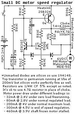
Reverse engineered circuit diagram of a motor speed regulator out of a portable pocket tape recorder containing a single motor for all functions. This circuit works amazingly well, keeping the motor speed constant regardless of shaft load and battery voltage.
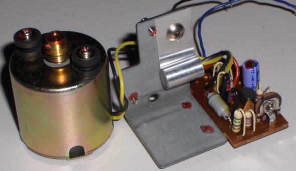
The choke is the gray cylinder immediately to the right of the metal bracket:
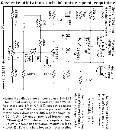
Reverse engineered circuit diagram of a motor speed regulator out of a line powered Cassette dictation machine containing a single heafty motor for all functions. This circuit works amazingly well, keeping the motor speed constant regardless of shaft load.
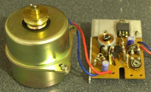
Notice the choke just below the heatsink to the left of the power transistor:
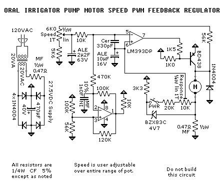
Reverse engineered circuit diagram of a PWM motor speed regulator out of an oral irrigator water pump. This circuit works quite well, keeping the speed of the small PM motor fairly constant regardless of load. No transistor heatsink is required since this is a switching regulator. The efficiency under high load would be a improved if the output transistor was made to switch faster. That could likely be accomplished by using a FET in place of the bipolar and then adding a mild positive feedback path to the upper comparator.
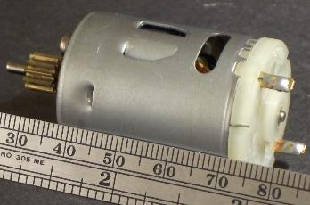
This motor is larger and more powerfull than it looks in the picture:
Safety, accuracy and completeness of information provided herein is not guaranteed,
so be inspired by it but do not use it as a basis for experimentation or other actions.
 |
TOP | ©™ |
|
|
Version 20231217